Trilobite
1.4
User Guide
|
|
Trilobite
1.4 |
|
|
|
|
|

The
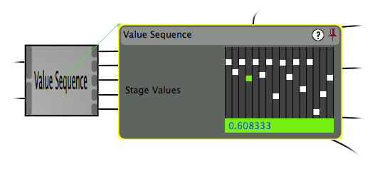
Value Sequence Module implements a 16-stage triggered sequencer with
adjustable direction and wrap-around positions. This module is useful
for complex internal control within a patch, and is often well paired
with the Sample Hold Module to create musically interesting extended
sequences. See this cool
tutorial by Doug Lynner
to see a similar example on the Serge Analog Synthesizer.
To set sequence values in this interface, simply click on one of the small slider thumbnails in the slider array and drag up or down. Note that when you do this, the thumbnail is colored green and the text box on the bottom displays the slider numeric value. To make fine tuned adjustments, hold down the shift key while dragging, or enter the value directly into the text box.
For a key to understanding the following tables, see the Module Types page.
|
|
The Value Sequence module is available in Pro Version only. |
Adding input ports is not enabled for this module.
|
# |
Title |
Type |
Description |
|
0 |
Stage Values |
Sequence Value Array |
The sliders in this parameter user interface adjust output values at each stage in a sequential sequence (it's really 16 parameters in one). Parameter values have the range [0, 1]. |
|
# |
Title |
Description |
Input Scalar Used |
Parameter Scalar Used |
|
0 |
Step Trigger |
When the parameter-scaled value of this input signal rises above 0.5, a transition to the next sequence stage will occur, where the next stage is determined by inputs to Ports 3 & 4. |
NO |
YES |
|
1 |
Quantization Factor |
For non-zero input signal to this port, the Value Sequence will lock to proportionately quantized output values. |
NO |
YES |
|
2 |
Smoothing Factor |
Input this port will determine the degree of intermediate smoothing which occurs between subsequent values as the sequencer moves between stages, allowing the output to move from sharp transitions (for input zero), to extremely smooth and rounded ones. |
NO |
YES |
|
3 |
Start Stage Offset |
This input signal indicates the address, in the form of a ratio in range [0,1], of the first stage in sequence playback, in other words the stage the sequence will loop back to when it it leaves the end stage. This value may be larger than the End Stage Offset signal routed to Port 4, in which event the sequence runs backwards between the two addresses. |
NO |
YES |
|
4 |
End Stage Offset |
This input signal indicates the address, in the form a ratio in range [0,1], of the last stage in sequence playback. When the sequence leaves this stage, it next steps to the address specified by the Start Stage Offset signal. This value may be less than the Start Stage Offset, in which event the sequence runs backwards between the two addresses. |
NO |
YES |
|
# |
Title |
Description |
|
0 |
Output Value |
The current active stage value in the sequence, or a smooth transition if the stage is changing. |
|
1 |
Stage Counter |
A value in the range [0,1] which indicates the address of the currently active stage in the value sequence. |