Trilobite
1.2
User Guide
|
|
Trilobite
1.2 |
|
|
|
|
|

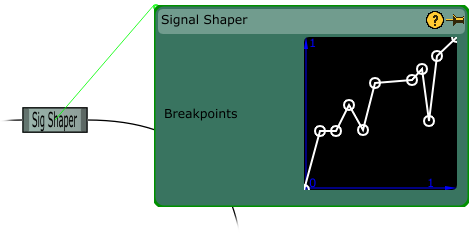
The Signal Shaper Module applies digital distortion to its input in the form of a functional map. The scaling map serves as a mapping of input signal amplitude on the X-axis to output signal amplitude on the Y-axis.
If the patch is active, results of breakpoint editing may be heard in real time.
This distortion map is intended to operate on signals in the range [-1.0, 1.0], and the input signal will be clamped accordingly. Output signal will always be in the range [-1.0, 1.0]
For a key to understanding the tables on this page, see the Module Types page.
Adding input ports is not enabled for this module.
Static parameters for this module are an array of up to 16 breakpoints which define the function envelope. These breakpoints may be edited using the editor interface shown above. The breakpoint editor may be used as follows:
To add a new breakpoint to the envelope, double-click in the desired position and the breakpoint should be added immediately.
To delete a breakpoint, double-click on its circular boundary.
To drag a breakpoint within the area spanned by its two closest neighbors, left-click and drag the breakpoint to a desired position and release (breakpoints may not be dragged past each other).
|
# |
Title |
Description |
Input Scalar Used |
Parameter Scalar Used |
|
0 |
Input (Index) Signal |
The input signal which will be distorted by the map function. |
NO |
YES |
|
# |
Title |
Description |
|
0 |
Distorted Output Signal |
Function map distorted version of the input signal. Range: [-1.0, 1.0] |